Best way to jump-start Microchip PIC Programming
Microcontrollers are very powerful and useful in building DIY projects.
Together with several pre-built modules (sensors and actuators), we can do rapid prototyping and construction of several mechatronics and robotic projects. Among the many makers of microcontrollers, the PIC microcontrollers from Microchip (wwww.microchip.com) is my device of choice because of its wide availability, cheap price, wide range of chip selection and the most important of all, ease of programming. Also, The chips requires very few components to run thus making the circuit less crowded. If you want to know more about PIC Micros, visit this part of my blog (the link is coming soon!).
Although PICs are very useful, the task of programming it is a bit of a turn-off to those who are not very keen in programming. But worry no more. Even with no programming experience, let me show you how to program and use you PIC chips the way they are intended to be.
The things you will need:
1. A PC (personal computer with a USB port)
2. the very famous Pickit 2 Programmer. The Pickit2 can be bought with the Low Pin Count demo board provided with the PIC16F690 chip. If you don't have the demo board, just secure the 16f690 and a breadboard. Together with a few wires, a 0.1uF capacitor we can connect the PIC MCU to the Programmer without the demoboard. Also, this approach is useful if we want to program chips other than the 16f690 specially those that having a different pinouts (pin assignments), have more than 20 pins and those generally will not fit on the ic socket in the LPC board.
We can add some 330 ohm (1/4 w) resistors or any value between 200 to 400 ohms (just to protect the leds), and a couple of Leds for a simple demonstration of our program.
The breadboard setup is shown Fig 3 and 4. A separate blog entry will be made soon to explain the circuit connections and construction.

Figure 1.
The PICkit 2 Programmer from Microchip
3. A demo copy or trial version of Flowcode (www.matrixmultimedia.com)
In this guide, I am using Flowcode 5. You can opt to use the latest version ( version 6) which is free to try for 30 days. A copy of the microchip Pickit 2.61 Programmer software.
Note: the PICkit2 sw can be integrated in to flowcode using the correct configuration.

(a)

(b)
Figure 2
(a) The Flowcode 5 for PIC MCUs
(b) The GUI of PICkit 2.61. The installed/connected PIC MCUs name is displayed if properly connected.
A little bit about FLOWCODE...
Flowcode is an easy to use, flowchart style programming software for MCUs. The Version for PIC Micros support several well known MCUs and the demo version can be enough for beginners.
If you know and can understand flow charts, then you can program your PICs.

Figure 3
Connecting the PIC MCU on the programmer using a breadboard

Figure 4
PIC MCU on a breadboard and to be connected to the PICkit 2 Programmer
Let's begin Programming...
For our first try, lets use the usual Hello World program where we just want to use our PIC micro to turn on an LED. After this, we will make another one program that will allow our LED to blink. Note that the microcontroller can be programmed and reprogrammed 100,000 times so one chip would be enough to learn several programming skills.
Hello World!
Step 1. Open Flowcode
2. click on Create a New Flowcode flowchart
3. Select the PIC 16f690

Figure 5
The flowcode GUI should look like this:

Figure 6
A: the command toolbox. We flowchart commands that we will be using during programming
B: Our program (flowchart) Empty for now.
C. Component tool box. We can simulate our program using these components and see if our program runs and does what we want it to do.
D. The pinouts and pin labels of our pre-selected PIC MCU.
E. The properties of the component we we selected.
F. The component panel where we will put the components we will be using.
Since we want to turn on an LED, we need to use the i/o ports of the 16f690. For a detailed information on the ports and features of the PIC, you can download the datasheet here:http://ww1.microchip.com/downloads/en/DeviceDoc/41262C.pdf
We will use RC0 of Port C because it is connected to the LED and and pull up resistor in the LPC demo board. Also, the LED is connected to this port in the circuit shown in Fig.4.
To turn on the LED, we need to set RC0 as an output and set it to high.
Step 4. Click on the output icon in the command tray (Fig.6 A), hold and drag it to the line line connecting Begin and End in flowchart.

Figure 7
Step 5. Double click on the Output icon in our flowchart and the the output properties window will pop-out. Select Port C on the Port selection and select Single Bit and the 0 on the Output to...

Figure 8
Don't forget to type a value of 1 (for high) on Variable or value selection.
That's it and our program is done! Our flowchart should be the same as Figure 9.
All we have to do is compile it to generate the hex file that we need to transfer the program to the pic. Before we do that, we can also what this program will do by doing a simple simulation.

Figure 9
Optional steps (simulation):
(You can go directly to step 8 if you do not want to simulate your program)
Step 6. Click on output then LED on the output icon on the component toolbox.
A small red circle representing an LED will appear on the component panel.

Figure 10
Step 7. This LED must be connected to the output pin that we just to high (RC0).
Right click on the red LED in the panel then select Connections...
In the Specify Components Pin Connections window, clicd on LED, then select Port C on Port and 0 on Bit selection tab. This connects the LED to RC0 in our simulation.

Figure 11.
The Simulation Panel is Complete. Click on Run in the Main toolbar and you should see the LED turn on in the Panel.

Figure 12
Compiling our program:
Step 8: At this point, we have not yet configured flowcode to work with our Pickit2 Programmer so for the time being, we will just generate the hex (the language of the PIC) file and use the Pickit 2.61 Programmer software to "burn" or put our program to the 16f690 chip.
First we need to configure the chip itself.
In Flowcode, click on Build in the main Menu, then Project Options...
In the Project options window, click on Configure chip.
In the PICmicro configuration window, click on Watchdog Timer and Select off.

Figure 13.
Remember the CONFIG value, in this case it is 0xFF7
Step 9: Save the program as "Hello World.fcf".
Next, generate the hex file. Click on Build, then Compile to HEX...
Wait for the compiling process to finish.
After this you will find a file named "Hello World.hex" added to the folder where you saved the "Hello World.fcf file.
Step 10. Burning our Program to the PIC.
Open the Pickit 2.61 software ( Pickit2 should be connected to the PC).
The Pickit 2.61 software window should say "PIC Device Found"
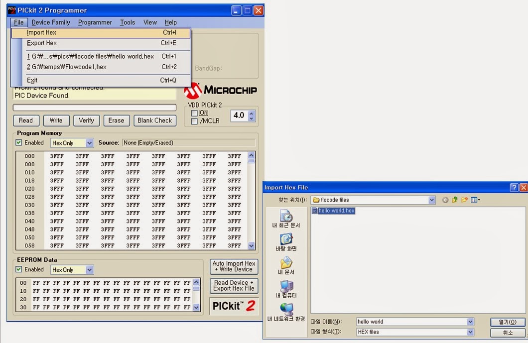
Click on File then Import Hex...
Select the "hello world.hex" file in the proper folder.
Open the Pickit 2.61 software ( Pickit2 should be connected to the PC).
The Pickit 2.61 software window should say "PIC Device Found"
Click on File then Import Hex...
Select the "hello world.hex" file in the proper folder.
Figure 14
You should see the message "Hex file successfully imported"
Also you should see the configuration value and it should be 0FF7.
Set the VDD Pickit 2 to 4 (meaning 4 volts) from the original 2.5
Click on Write to begin loading our program to the PIC. After this.
you should see the message "Programming Successful".
That's it. The program is already in the 16f690. You can click on the on button on the VDD Pickit 2 to supply the PIC with 4V and you should see that the leftmost LED in the LOw Pin Count Demo bard)which is the one that is connected to to Port RC0 to light up.
Figure 15.
No comments:
Post a Comment